

 |
 |
|
|
OSAA Skilt 2.0
Dioder plus Softwarehack equals Lightshow
At the local hackerspace OSAA, Brix made a
Plexiglas sign with a milled logo late last summer and had the brilliant idea
of using the Ikea DIODER gadget. Then, Rohde made the first software
hack and a solder-less programming interface (see below). He reprogrammed the
gadget to show some colors, but the project stalled soon thereafter. Writing
software is hard work.There have been several hacks using the dioder gadget (again recently at hackaday), referring to a nice description of the hardware by Christian Amsüss. However, all these hacks lack a feature rich software replacement. Sure you can write it yourself, but writing software is hard and requires a lot of time. Then I decided that there was significant need for over engineering and suggested some ideas. With a "What?" reception of my vision and a "You do it" attitude, I started coding.
The features envisioned:
IndexHacking the gadget is not easy when you need to program it many times. Especially the "real thing" is in circuit and not easily accessible. But when I wanted to buy a new one at the local furniture pusher, they were sold out, sigh. Then I remembered that the Pickit2 came with a dev-board with a PIC16F690, which is basically the same as the PIC16F684 (which is used in the dioder), just has a few more pins and modules. I decided to make a mock-up version on my breadboard to hack the software while relaxed at home.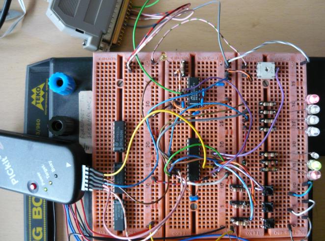 The mock-up has RGB LEDs on the output, three switches, potentiometer for analog input, extra LEDs on the unused pins and a serial input from a RS232 level shifter. It is directly powered from the Pickit2 and can be reprogrammed on the fly, without any fuss. The schematic diagram including the modifications: 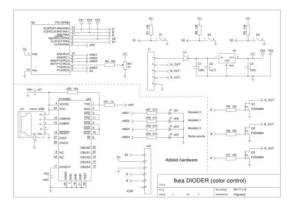 Schematic as PDF. Schematic gschem source. First implemented change was the addition of the extra LEDs (IND[1..4]). A couple of 0805 smd LEDs and resistors are soldered on a small veroboard piece and placed beneath the plastic. The PCB is held in place with a bit of hot-glue. The LEDs are luminous enough to be clearly seen through the case.
Running ModesButton S2 advances the running mode (cyclic) from the list below. Mode-settings can be changed with the wheel while holding down indicated buttons.The buttons are mapped from left-to-right: S3, S2, S1 (as seen with the buttons at the bottom).
Serial ProtocolA two-byte sequence is used for communication, where the first byte (command) has the highest bit set and the second byte (data) has the highest bit cleared. The serial speed and format is 1200 Baud 8N1 (2400 is possible but not 100% reliable; any faster is not reliable at all).The host sends a command-byte followed by one or more data-byte(s). Each command is executed at the reception of the data byte. If multiple data bytes are sent, then the previous command remains in place and is used. The ommision of the command byte reduces the communication overhead for fast changing data.
Note 2: multiple data bytes are only useful if the initial command byte has the "activate immediately" bit set and the high bit(s) of the data does not change (except for direction or swap-command). Now that the software is running, more images of the inner life. 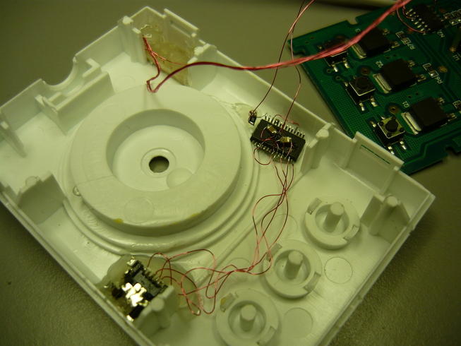 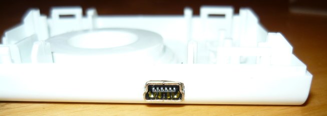 SoftwareThe entire stack is at OSAA's GitHub repo https://github.com/openspaceaarhus/ikea-sign.The firmware is complete and functional. It should run on any DIODER gadget with or without the additional hardware. The firmware uses the EEPROM to store the configuration (yes, you can configure it). Parameters include startup mode, speed, direction and color. Speed, color and directional information is stored in the EEPROM on each change. Storing the startup mode requires you to press B2 (holding down) and then additionally B1 and B3. Bugs: the added indicator LEDs do not change correctly when sending mode change commands over the serial port on the PIC16F684. This bug is not present on the PIC16F690 (my test chip). There is no functional impairment, just missing the correct visual indicators. So far, this bug has been classified under "programmer's brain-cells not smart enough to see the error". And, of course, a QT test-app to control the DIODER via the serial port (only reliably scans ttyUSBx devices): 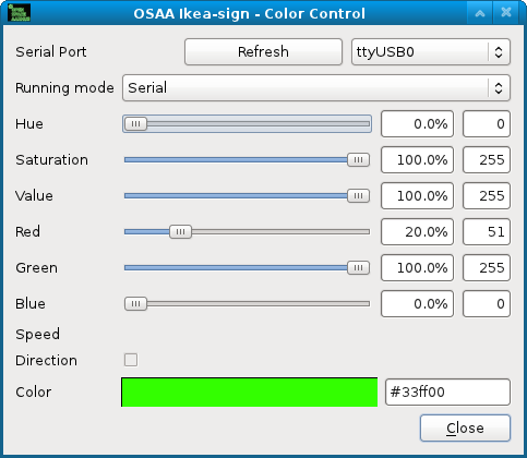 Todo: get the PC running with a daemon and a camera. Then show the world how they change the colors ;-)
Posted: 2012-01-04 |
||||||||||||||||||||||||||||||||||||||||||||||||||||||||||||||||||||||||||||||||||||||||||||||||||||||||||||||||||||||||||||||||||||||||||||||||||||||||||||||||||||||||||||
| Overengineering @ request | Prutsen & Pielen since 1982 |