

 |
 |
|
|
FlipTest
Flipdot test-setup
We got some flip-dot signs at the local
hackerspace and I got really fascinated about that old style tech. They are
so nice, fast and have a fantastic sound. Also, the projects done with these
flipdots are intriguing and make my fingers itch for experimentation. When
asked to look into a battery operated device, it was the right time to start
hacking.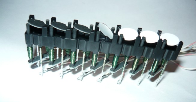 The flipdots are available in strips of 1x7 dots. Each dot has a coil which must be driven in +/- or -/+ direction to flip to white and black respectively. That means an AC signal on the coil and makes the driving circuit somewhat awkward. The second requirement is that a current of ≥350mA is maintained through the coil (driving the core into saturation) for at least 450µs to reverse the magnet's polarity. 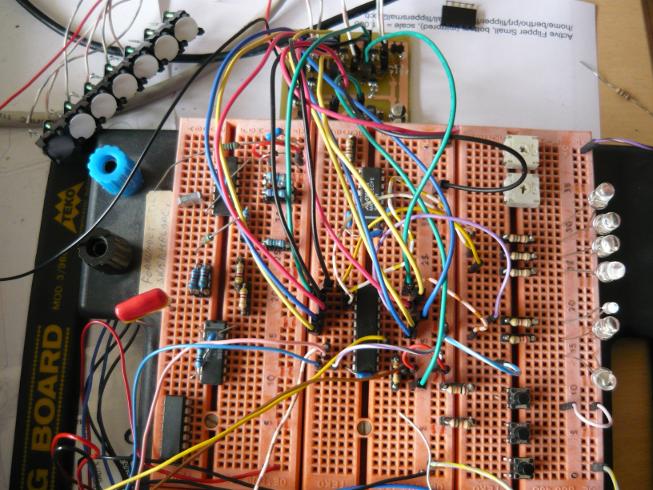 The applied voltage is not so much of a problem as long as it is high enough to drive the coil at 350mA. The coil's resistance is rated at 18.2Ω±10%. Therefore, the minimum driving voltage would have to be 7V (accounting for tolerances). The idea is to drive the coil in a series LCR circuit, where stored energy from a capacitor is discharged into the coil. This circuit will exhibit a typical voltage/current transient characteristic. The maximum current is automatically limited to a defined curve dependent on the values of L, C and R. The peak current will see no appreciable inductance (the core is saturated), but the maximum current will then hinge on the relatively large resistance of the coil. The flipdot documentation states (loosely) that the current will rise from 0 to 350mA in 50µs when a constant voltage of 24V is applied. This results in an approximate induction value of 3.4mH. A capacitor of about 100µF at a voltage of just over 9V should generate a current curve that has just about the right timing and maximum current (at worst-case tolerance). 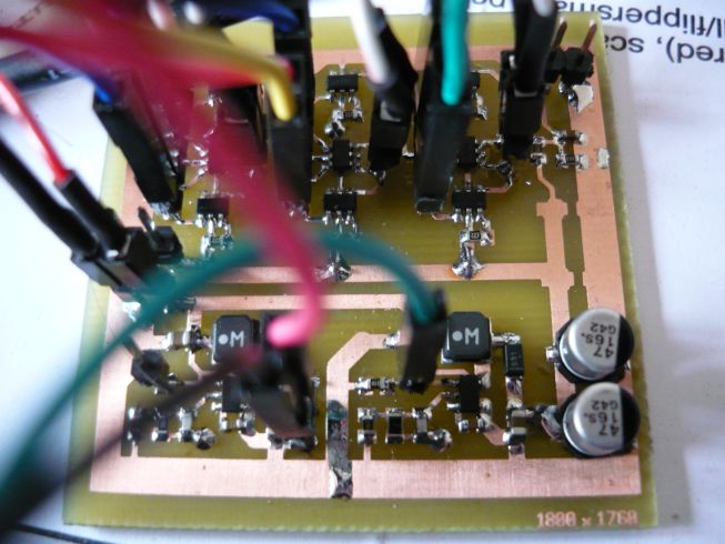 A test-PCB was created with two step-up converters, based on NCP1406, and some H-bridges. Actually, the H-bridge is a |-|-|-|-|-| bridge. There are six totem-poles where each center-tap is connected to a coil connection. All coils are connected in series (6 totem-poles can drive 5 flipdots). One step-up converter creates a 5V supply voltage for an embedded processor, which in turn drives the totem-poles. The second step-up converter is enabled under processor control and generates 9.1V, charging 2x47µF capacitors. Each totem-pole consists of two N-channel and one P-channel MOSFETs. The low-side is switched with an N-channel and the high-side with a P-channel. The high-side is level-converted using the second N-channel. A flipdot is controlled by enabling the step-up converter and let it charge to 9.1V. When the charge is reached, then the converter is disabled and a high-side and low-side part of two distinct totem-poles are activated. The capacitor discharges into the selected coil in the selected current direction, resulting in a flip of the dot. The totem-poles are deactivated after a selected interval. Rinse and repeat. A preliminary test shows that it works as planned; the dots flip. The current consumption of the setup hovers around 55mA at 20 flips/s, which is about the level that was calculated. More testing has to be done to see the current and voltage profiles and to see if the magnet-cores are properly saturated for long enough time. A small test-video from the dots running at 20 flips/s. [2013-03-19] Some images and conclusions after doing some more measurements (click to enlarge). The current pulse is measured over a 0.2Ω resistor in series with one of the totem-pole outputs.
You can see a small tangential break in the current rise on all images at about 320mA. This is the point where the core reaches saturation, where the inductance is reduced to virtually non-existent. So, gathering from the images, we can be sure that saturation has been reached. A look at the voltage curves. The top trace is the enable of the power supply. The capacitors are charged when the enable is high (at 5V).
Measuring the input supply current over a 1Ω resistor in the ground return-path reveals that the PSU is way too active at ~715mA peak. The step-up conversion is limited in the first 1ms (soft-start), but then limits on the switch-frequency.
The drain on the batteries is substantial, event though the input current is limited to 3.5 to 4ms. When the batteries are fresh, this is no problem. However, old batteries, with increases internal resistance, would suffer. The coil must be reduced to ~1µH as to get into current-limit faster, allowing the coil to drain before the switch is turned on again. [2013-03-26] The power drain issue is resolved after some more thinking. A current-mode supply is needed instead of a voltage-mode supply. The issue is not purely of coil size, but the current to charge the capacitors. In voltage-mode, the supply will simply generate as much current as possible, regardless. The current to the capacitors must be limited if the battery-drain is to be held within reasonable values. Hence, a current feedback on the power-supply solves the problem. 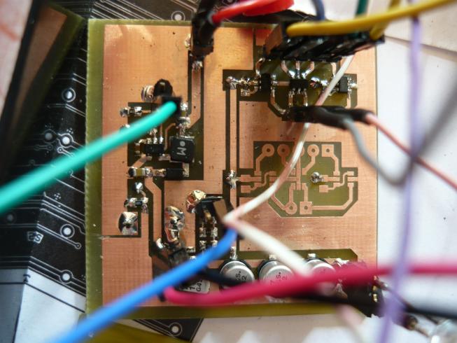 The NCP1406 even has an example in the datasheet how to achieve this. A 59Ω resistor is put into the ground-line of the 4x47µF capacitors (and decoupled with 10nF). This limits the current to about 20mA. The output voltage for a full charge will be 9.1V plus 1.19V of the feedback line. The micro-controller senses the capacitor voltage and disables the power supply when the correct charge is reached. The decoupling capacitor on the 59Ω resistor ensures that pulses on the H-bridge MOSFETs will see little resistance with respect to ground. It also filters the high spikes on the feedback line. A battery-test runs on the new power supply with the changes in place on a new test-PCB. The maximum input current is now limited to about 100mA with 2.9V on the input, which is an acceptable value. The input current rises as the input voltage drops to transfer the same amount of energy. This will accelerate the battery aging, but is still acceptable. If the current turns out to be too high, then a larger resistor could be used. The tests will show which way to go. 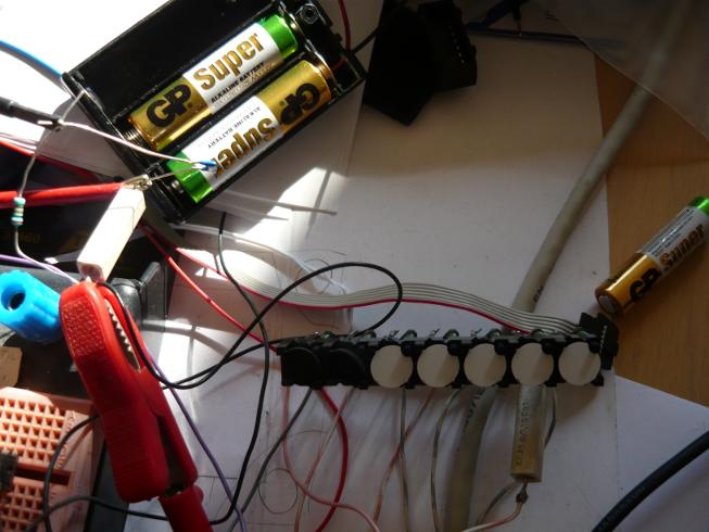 The batteries run down after running 48 hours at 17 flips/s. The test-CPU runs at 5V and without any code optimization such as sleep and such. The base-current draw is at 10mA without flipping (about 8 times higher than necessary). The system fails to flip properly when the two AA batteries reach just under 1.4V. This is also close to the point where the NCP1406 will stop functioning and just under the asserted hold-limit of 1.7V. 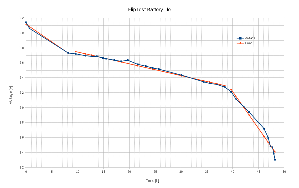
Battery voltage curve over time (click to enlarge)
The system managed to do 2.95 million flips before failing, which extrapolates to 34 days at one flip per second. This extrapolated estimate assumes that the final CPU setup draws a lot less power than this test, but that should be a minor issue. Secondly, the test loads the batteries very hard, whereas a 1 flip per second system allows the batteries to recover better between flips (between high loads), which should give 5..10% extra power. It should be noted that the used alkaline batteries perform as documented, presenting three distinct time-voltage curve sections. An estimated 2500mAh was drawn from the batteries, which is quite well in accordance to the specification. Most AA batteries are between 2000mAh and 2900mAh, so the system will probably work for 30..40 days before replacing batteries.
Posted: 2013-02-19 |
| Overengineering @ request | Prutsen & Pielen since 1982 |