
 |
 |
|
|
Capacitive Sensing, the Hard Way
Part 1 - Measuring Capacity
This entry is the winner of the Grand Prize in the 7400 Contest. Thank you. A touchscreen is an interesting interface. I've been interested in interaction by means of touch for a long time. While pondering my next project, I wanted to make my own touch interface. Sure, you can buy a resistive screen and go from there, but there is a challenge in making your own screen. Also, you do not want to use force to activate. So, capacitive sensing is the way to go (yes, you can go IR too, next project, maybe). An extra benefit of capacitive sensing is the possibility of detecting proximity, and with proximity you open up an extra dimension of interaction.
Now, you can do capacitive sensing using either PIC or AVR microprocessors.
Both Microchip and Atmel have descriptions on how to do it and software that
goes with it.
Capacitive sensing principlesThere are basically two ways to do capacitive sensing:
What has this to do with the 7400 Contest? Well, I want the best of both
worlds. In the microprocessor case, you have to decide for either method 1
or method 2. You cannot use both at the same time. PIC and AVR
microcontrollers have a limited measurement capability. Their master-clock is
often too slow to do anything too fancy. And, what is the point in using 100%
of your CPU cycles for your input detection? You compromise. Designing, the old-fashioned wayThe spec of the measurement system is as follows:
Counting pulsesThe constant time measurement is done measuring the frequency of an RC oscillator. Strictly spoken, we could, of course, measure the exponential curve for constant time measuring, but that would a) require an accurate A/D converter, b) a very fast A/D converter, c) several measuring points (three or more) and d) lots of processing power. We have none of these and therefore we go with measuring frequency.A RC oscillator is easily built with an inverting gate with a Schmitt trigger input. All we have to do is count the number of pulses that are generated within a defined period of time. The frequency is then defined by count/tperiod. The accuracy is +0/-1 counts. Counting fractionsTo improve on the accuracy, we can divide the pulses from the generator into small slots and see how many slots can be counted (measuring fractions). This can be done using a high-frequency master-clock which pulses are counted for each and every oscillator period. For example, if the master-clock is 30 times faster than the oscillator frequency, then we can improve the measurement by ~4.9 bits (). There will still be loss of accuracy at high oscillator frequencies, but 2..3 bits improvement are still worth the effort.Channel hoppingGoing through 16 channels can be accomplished by using analog switches. With a 50Hz scan-rate over all channels, we have 1/(50*16) seconds time for each channel. This also sets the absolute lower bound of the RC oscillator. We cannot measure any frequencies that are so low that we do not see (at least) several periods within one channel measurement's time span. A practical limit would suggest that we need at least several orders of magnitude between the RC oscillator and the channel-hopping frequency.Serial protocolHaving a lot of data is one thing, doing something with it is another. The data must be transmitted in a fashion that facilitates easy use. Information generated by the measurement:
Assuming that the data fits in 3 bytes and uses format 8n1, then the lowest bit rate is 16*50*3*(8+2) bits/s or 24000 Baud. Using standard baud rates we must opt for 38k4, 57k6 or 115k2 (for the purists: I know that the standard only goes to 9k6 or 19k2, depending version. However, most computers, since at least the mid-80ies, can go to 115k2 or more.). The 7400 DesignThe features implemented:
Schematic diagram 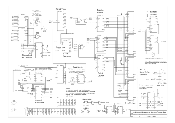 Timing details and data format 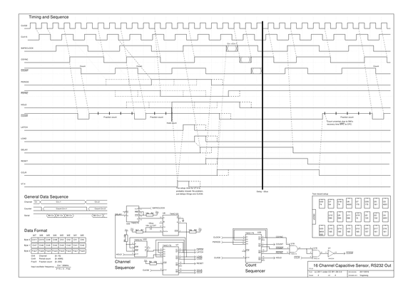 Schematic and timing as PDF. GSchem source of schematic diagram. GSchem source of timing diagram. The Inner WorkingsWarning: Using 7400 logic at a frequency of 30MHz is a pain. You have to realize that the propagation delays are in the same order of magnitude as the clock frequency. This makes it not only hard to design, but also hard to debug. Using an oscilloscope can be a daunting task as the probe's capacitance (~10pF) delays the signal you are measuring. When looking at a cycle-time in the order of 33.3ns, you'll find that 1 (one) nano second is an eternity.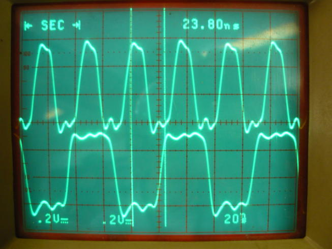 The above image shows the propagation delay (tpd) of the CLK30 (upper trace) vs. CLK15 (lower trace) signals. Note that the CLK30 signal has one more inverter in the chain, so that the CLK15 signal is triggered on the falling edge. According to the datasheets, the '04 has a tpd of 6ns and the '74 D-flip-flop has a tpd for CP-to-Q of 14ns. With the measured time of 23.8ns we can see that it fits very well: 23.8 - 0.5*33.3 ~ 14 - 6; the gates are actually slightly faster than the datasheet's typical tpd. Master ClockThe 30MHz master clock (CLK30) is designed around a '04 inverter in a standard oscillator setup. The primary output of the oscillator is buffered once before it is used to make sure not to put additional load on the oscillator. Care has to be taken for start-up stability and the primary problem is to match the crystal with the load-capacitors. The master clock is the primary source for synchronization and fraction countingThe master clock is divided by two using a '74 D-flip-flop to generate CLK15 and divided by two once more for CLK7_5. These clocks are used to feed the baud rate generator, the period timer and the clock monitor. Channelized RC GeneratorThe capacitive inputs are selected using 74xx-ized analog switches ('4051). The channels are selected using a synchronous '161 counter to feed a RC-oscillator build around a couple of '132 Schmitt-trigger nand-gates. The channel counter can be put on hold using the DTR signal from the RS232 port. The counter is automatically advanced by the channel sequencer (if DTR enabled) after the measurement period.There is of course a 16-to-1 analog multiplexer available, but it comes in a 24-pin package and that is monster size compared to the 16-pin package of the '4051. Besides, we need at least one inverting Schmitt-trigger gate and the options are 6- or 4-in-a-package. No reason to let the gates go unused. The design, as is, uses one extra analog switch package, but still saves space on the board. Period TimerThe capacitance measurement is timed with a '4020 14-stage counter fed with the 7.5MHz clock. The last stage output will be high after 215 counts of CLK30. The counter is reset at the start of each measurement so that all channels have consistent period timing.So, you thought that it would be 215 counts? Think again! The '4020 is a ripple counter and has tpd of 11ns for CP-to-Q1 and 6ns Qn-to-Qn+1. This means that the counter is 11+13*6=89 nano seconds late at Q14, or almost three CLK30 periods. The real problem this introduces is not the delay in itself, but the loss of synchronization, which has to be fixed. Period CounterCounting the number of clocks generated by the RC-oscillator is one of the primary goals of the system. It uses two '590 8-bit synchronous counters in synchronous cascade. Only 12 bits are used for the final result, which sets the upper boundary condition for the input frequency. The counter will overflow at 30MHz * (212 - 1) / 215 ~ 3.75MHz. This is an approximate value, because the period timer is not exactly 215 counts and the count sequencer also plays a small role.The '590 chip has a nasty habit of not providing the counter output immediately, but it needs to be clocked into an output register (using the RCLK input). The channel sequencer takes care of that part at the appropriate time. Fraction CounterThe second goal, to provide more accuracy, is performed by the fraction counter. This counter, also an '590 chip, is clocked at the master clock frequency of 30MHz. It is set up in such a way that it will count CLK30 periods for each and every RC-oscillator period (CLOCK period). The counter is reset at the start of a period and then counts how many 33.3ns slots fit into the RC-oscillator's period. It is important that no CLOCK periods are skipped because this counter is independent of the RC-oscillator and the period timer, so we have no idea when the period timer will fire.The '590's 8 bits also sets the lower bound on the RC-oscillator frequency. A CLOCK period must be no longer than 28-1 CLK30 counts, or about 0.117MHz. Any lower frequency would overflow the counter. Note that there is nothing in the system that prevents it from measuring lower frequencies. There is just a loss of accuracy. Count SequencerA sequencer is used to put the period counter and fraction counter in the right balance. It is built around a series of D-flip-flops of a '175. Both the period timer's output PERIOD and the RC-oscillator's CLOCK are synchronized with the CLK30 master-clock. Basically, the '175 is used as two 2-bit shift registers. The effect of this is that CLOCK and PERIOD can be compared to each other without being afraid of glitches.The CLOCK signal is converted into CSYNC in shift stage one and COUNT in shift stage two. These two are then used to generate the counter reset for the fraction counter. The PERIOD signal is converted into PSYNC and HOLD in shift stages one and two respectively. The HOLD signal indicates to stop all counting as it signals the end of the measurement. For the detailed sequence see page 2 of the schematic diagram, which shows the entire timing sequence. Channel SequencerHopping through all the channels is quite a task. The results of the measurement need to be transfered to the output stage, the channel counter must be advanced and the period timer reset. A series of D-flip-flops in a '175 chip, like above, are set up in a shift-register fashion. However, the advancement of the sequencer is not only dependent on the HOLD signal (which indicates the start of the sequencer), but it also depends on the RC-oscillator clock and a delay to let the next measurement channel settle.When the HOLD signal fires, the first thing is to load the outputs of the '590 counters with the LATCH signal to make the measured data available. The LATCH signal is a single pulse initiated by the rising edge of HOLD setting the output of a '74 D-flip-flop. The '74 is then reset by the LATCH signal so that only one single CLK30 period propagates through the '175. Stage two in the sequence activates the LOAD signal, loading the data in the serial output stage. The LOAD signal also activates a '123 timer set at ~33 micro seconds. This time is used to let the RC-oscillator settle in the next channel selection. The propagation of the pulse through the '175 is now delayed until it is synchronized with the (SAFE)CLOCK from the RC-oscillator. The reason is that it must be guaranteed that the measurement start of the new channel is exactly on a CLOCK period boundary. Otherwise, we'd see +/-1 variations on the count output with stable input frequency. The activation of the '123 timer also signals the serial output on the DSR line that data will be forthcoming. The receiver can then synchronize with this to know when the first byte of a data-set is sent. The period timer is held in reset while the '123 timer is active (RESET signal) and the channel counter is advanced at the rising edge of CCLR. Both RESET and CCLR are kept active for the settling period. After ~33 micro seconds, the CCLR signal resets the '590 counters and the new measurement begins. For the detailed sequence see page 2 of the schematic diagram, which shows the entire timing sequence. There is a small variation in the scan rate introduced here. The constant time rate is modulated with the synchronization of the (SAFE)CLOCK signal. The next channel is delayed because the sequencer waits for the RC-oscillator. However, this delay is two to three orders of magnitude away from the actual scan rate. Additionally, the clock monitor will prevent variations larger than 15 micro seconds. Who is counting micro seconds in a milli seconds world? Clock MonitorA problem exists in the channel sequencer if the capacitive input(s) are not functioning. The channel sequencer can only advance through the complete cycle if and only if the RC-oscillator is running. When an input is shorted to ground or Vcc, then the sequencer would get stuck. The clock monitor prevents this from happening by using the re-trigger functionality of a '123 timer. If, for any reason, the RC-oscillator stops, then the timer will expire at about 15 micro seconds. This will then switch the '157 multiplexer into selecting the CLK15 signal instead of CLOCK. The channel sequencer is then free to advance to set up the new channel measurement. Once the RC-oscillator is running again, the multiplexer automatically reverts to the CLOCK input.The SAFECLOCK signal is not guaranteed to have a frequency above the monitor threshold. A channel that is stuck will result in a zero count in the period counter. Whereas a low frequency input signal is counted by the period counter, but will be prevented from stalling the sequencer too long. Baud rate GeneratorThe RS232 serial output requires a fixed clock of 115.2kHz to shift out the bits onto the serial port. The master clock runs at 30MHz and that means a division by 30MHz/115.2kHz ~260.42. We could, of course, do fancy divisions, but there is no need. Dividing CLK30 by 260 would result in 115384.6Hz, which is 115k2 plus 0.16%. That is close enough.There is a crystal at a frequency of 29.4912MHz, which would create a perfect 115k2 rate with a division factor of 256. However, at the time of building this contraption, there was none available at the shop, so I settled for 30MHz instead and let some gray cells ponder a suitable division. The 260 division is a problem because it is more than 8 bits. However, CLK15 divided by 130 yields the same result. Two '161 synchronous counters are cascaded to generate the division by 130. The '161 counter has a synchronous parallel load, which can be used to preset the counter, making it possible to do fancy counting. The parallel load value is set at -130 (minus 130), which, in 8-bit truncated two's complement binary, is 01111110. The '161s will then count up to 11111111 and the ripple carry output is set. At the next clock the parallel load value is again loaded and the process starts again. This is effectively a divide-by-130 counter. It must be noted that the ripple carry output of the '161 counter is not glitch-free. This is important because there is in fact a glitch on it (found out the hard way). So the carry out cannot be used as a clock output. However, the highest bit in the counter has the same frequency with two CLK15 periods low-time, which is fine as a baud rate clock. Finally, the baud rate generator is reset every time new data is latched into the '590s counter outputs. This is necessary to ensure the validity of the serial data. The baud rate generator operates independent of the measurement timing and that could result in a baud rate clock pulse (B115K2) too close to the data transfer from the counters into the shift registers. Therefore, the baud rate generator is reset to guarantee an idle-period on the serial output at the time of new data. Serial OutputThe measurement data is transfered from the '590 counters to four cascaded '165 parallel-in-serial-out shift registers. There are 24 bits of data to be sent; 12 bits period counter (Cnt{0-11}), 8 bits fraction counter (Frac{0-7}) and 4 bits channel information (Q{0-3}). That makes 3 bytes of data. The data bits also need to include start- and stop-bits, which are an additional 6 bits. Finally, we must ensure that the serial data, at the time of loading and when done shifting, generates an idle condition on the TX line (a logic '1'). That means that the first and the last bit in the cascaded shift register are static '1'. When there is no more data available, the TX line is kept idle by re-inserting idle-bits into the shift register's serial cascade input.The bit-order in RS232 is LSB first, while the '165 has a (named) convention of MSB first. Therefore, data is physically connected in bit-reversed fashion with respect to the '165 naming convention. Once the LOAD signal is released, the baud rate generator will work through all the bits, transmitting them to any connected computer. It should be noted that the parallel load on the '165 is level active. Therefore we reset the baud rate generator before the parallel load. Otherwise we could have a B115K2 pulse that works glitchy. The data is sent in following order:
RS232 Level ShifterThe final part in the design is, strictly seen, not required for operation. And is, because of its non-7400 nature, marked as optional. The level shifter, a MAX202, converts the RS232 signal levels of +/-15V to TTL logic level. The nice thing about the level shifter is that it has pull-ups on-chip, which helps to set the default (active-) level for the DTR input. However, you could always put a pull-up on it, but things for free are things for free.Building the Real ThingNow that we have a design we need to make it too. So, I made my way to the local makerspace Open Space Aarhus, got my stuff spread out on a table and this is the result: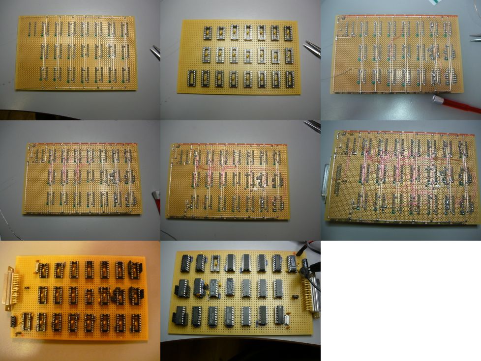 It took about 6 hours to solder all the connections. There are really many... As you can see, all bypass capacitors are mounted under the chips (in the socket), connected directly to the power supply pins. If you miss a bypass capacitor in such high-frequency design, you are toast, things will simply not work. First ResultsPower was put on the board without delay after soldering was done, and surely, the polarity was put on right. No smoke or nasty smell was detected with a power consumption of about 275mW (5V*55mA). But, as you might imagine, there are always some problems with systems of this complexity. This was no exception.The first problem encountered was the master-clock oscillator. The crystal is a 3rd overtone type and it was not running at 30MHz, but got stuck on the base-frequency of 10MHz. Touching the leads of the inverter made the frequency hop over to 30MHz. There has to be done some work on tuning the capacitive load on the oscillator. Second problem was more nasty, but still easy to solve. For the observant, there is a chip difference in the build and the schematic drawing. The problem was that the channel sequencer was lacking the '74 D-flip-flop to feed the HOLD signal to the '175. I mistakingly used a simple gate instead of the edge-triggered flip-flop, and that made the LATCH output oscillate at 15MHz for a CLOCK period. So, instead of a fine single pulse propagating I had a pulse-train propagating. Luckily there was "plenty" of space left to add one more '74 and make sure that only one pulse would be generated on the HOLD activation. It also provided me with one extra D-flip-flop used for the third problem. The third problem was that I, apparently, lacked the
ability to count to 215. The period timer was originally fed with
CLK15, but that means that Q14 of the '4020 activates at 214. That
is a whole factor of two short of the plan. Two possible solutions offered
themselves: connect the baud rate generator to the '4020 and use output Q8, or
use an extra divide-by-two on the CLK15 line. Because of the previous issue,
there was a '74 D-flip-flip unused, so the nice thing to do would be to
generate CLK7_5 and use that to feed the '4020 period timer. After fixing these problems there is a functional device: 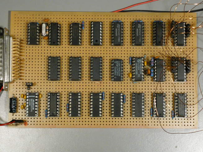 And with the touch-panel attached. 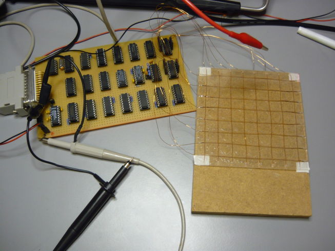 Just beneath the crystal is the extra '74 chip mounted. You can also see my improvised capacitive touch-panel, which is detailed in part 2. But on we go to do some computer work and see if we can receive the serial data. Computer ResultsFire up minicom on /dev/ttyUSB0, set parameters to 115k2, 8n1 and see what happens. Bingo! There is junk coming in. Assured, this was a proud moment, it looks like things actually work.A quick software hack was needed to take in the data and see if it made sense. A command line utility was written in the most simple form: take input from stdin and find the channel data (running it with $ ./chanread < /dev/ttyUSB0). Eventhough the DSR line can be used to find the start of the data, it is actually easier to scan the data for the channel identification. In the data stream you know that the low nibble of the first byte in any 3-byte set is the channel, which counts 0,1,2,...E,F,0,1,etc.. It is relatively easy to sync up with the data stream when looking for 16 consecutive channels. The chance of failure is remote as the rest of the data will be all over the place. A simple sync procedure looks like: /* Synchronize to input data stream */ void sync_datastream(void) { int i, ch; retry: for(i = 0; i < 16; i++) { ch = getchar(); if(i != (ch & 0x0f)) goto retry; else { getchar(); /* Read the two other data bytes */ getchar(); return; } } }When returning from this function it is known that the next data byte is byte 0 for channel 0. It was soon determined that the data was coming out at the correct rate and was looking right. Time to visualize. A quick hack later with a small QT4 test-app. Please note that the test-app opens a named pipe ($ mkfifo myfifo) and is run together with cat in the form "$ ./app & cat < /dev/ttyUSB0 > myfifo" (a simple hack when you don't want to write complex modular config stuff). 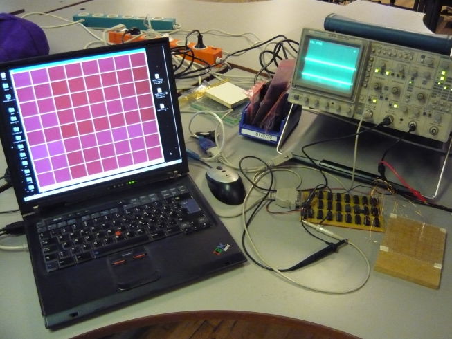 Each channel's data has to be converted into sane data. It is possible to use only the period counter values (12 bits), but the point was to get more accurate data. It can be determined from the timing of the system that the measured RC-oscillator frequency is: The "+3" is caused by the propagation delay of the '4020. /* Calculate the frequency from the data and extract the channel identification */ int calc_frequency(uint8_t data[], int *channel) { *channel = data[0] & 0x0f; /* Low nibble is channel */ int cnts = (data[0] << 4) + (data[1] & 0xff); int frac = (data[2] & 0xff); return (int)((int64_t)cnts * 30000000LL / (int64_t)((1<<15) + 3 - frac)); }The QT application reads the 16 channels, which are divided into 8 rows by 8 columns. This gives 64 visualized cross-points. The image above shows the system in idle mode, where you can see small differences in the channel's idle capacitive load marked at different shades of magenta. The image below shows the active situation when one finger is on the touch-panel. 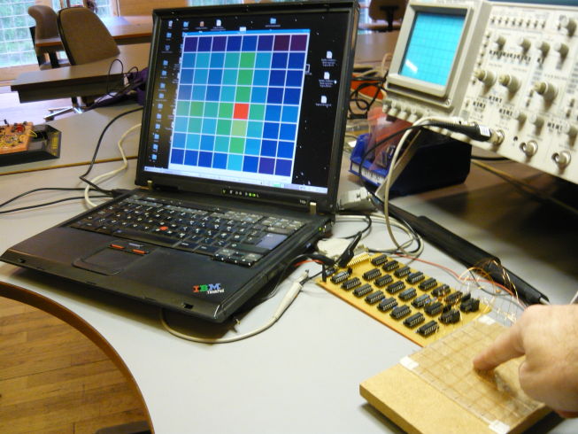 While the channel data is received, both maximum and minimum measurement values are recorded for each channel. The color on screen is based on the measurement span and provides a dynamic view. The color is calculated as the vector sum for each cell from the row and column data and mapped into a HSV cone on both Hue and Value with Saturation at maximum: /* Update channel c with input frequency f */ void update_channel(int c, int f) { fmin[c] = MIN(fmin[c], f); fmax[c] = MAX(fmax[c], f); if(fmin[c] == fmax[c]) ch_val[c] = 1.0; else ch_val[c] = (float)(f - fmin[c]) / (float)(fmax[c] - fmin[c]); } /* Get color for position x,y */ QColor get_color(int x, int y) { float vx = ch_val[x]; /* Channel 0.. 7 are columns */ float vy = ch_val[8 + y]; /* Channel 8..15 are rows */ float d = (vx*vx + vy*vy) / 2.0; return QColor::fromHsvF(d, 1.0, 1.0-0.8*d); }With some more hacking, the channels are mapped row/column on top/left to see what the individual channels' values are doing. This makes it easier to see that there is a need for adaptive amplification end decay. Something left for further analysis for the moment. First a better touch-panel must be produced. The final set up in overview; even a pen induces enough change in capacitance that can be detected: 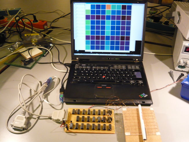 Video DemoConclusionWhat a funny project. Retro logic is good practice once in a while. It makes you think about the daily conveniences you have using micro-controllers and powerful PCs.On the technical side, there are some things that are not entirely as they should be, while others were very positive. To name a few:
So, now just get this into the 7400 Contest... Update(s)
Posted: 2011-09-14 |
| Overengineering @ request | Prutsen & Pielen since 1982 |