
 |
 |
|
|
Bang Head Here
Pain is no substitute for satisfaction
Gamification is a modern way of saying to take a piss with reality and do what
is, apparently, fun while creating something. An MBA would see gamification as
another way to get what (s)he wants while the other side is just as bad off,
but hopefully feels better about his/her situation. Whether or not a gamified
system is useful remains to be seen and may be determined by your peers.At least, that is the cynical view on gamification. To counter the cynicism, we can simply gamify a bad situation and have a good laugh at the same time. It is even more satisfying when the pun is lost on those who are the target, while bystanders see a funny device to be used for their own satisfaction. The funny thing is; creativity is often fueled by seeing a negative and converting it into a positive. So, we take a coping system, mangle it in the gamification engine, add some electronics sauce, apply engineering and look at the result. Now we can bang our head with just the right amount of force and get feedback about our state of mind while we are applying gamified self-punishment. Say hello to Bang Head Here. 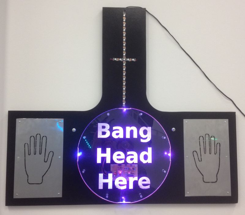
Design concept
With that in mind, it can be concluded that the right amount of self-punishment is a game of applying the right amount. That means a device can be built and measure "the right amount" for an arbitrary value of right. A second approach could entail the counting of how much self-punishment is left, but it is assumed that the person undergoing this self-treatment will be confused which direction to take anyway(*). A strip of indicator LEDs with a central bar is used to show the magnitude of self-punishment. The game's target is to apply enough power with your forehead to get to the middle of the vertical bar of LEDs. A piezo-buzzer is mounted under the acrylic disc as sensor to measure the magnitude of the bang and auditive feedback. The acrylic disc is furthermore side-lit for visual indication purpose. The game's operation is as follows(**):
Electronics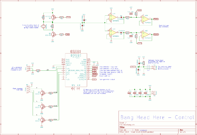
A voltage is generated in the piezo-buzzer when you bang your head on the disc. The voltage is detected in a high- and low-level peak detector to record the magnitude of the bang. The microcontroller records the peak levels by reading the PEAKL and PEAKH signals continuously and records the highest/lowest levels seen. The peak detectors can be reset with the clear signals CLRL and CLRH. A high level and low level on CLRL and CLRH respectively will take the peak detectors to the opposite end of the detection range. The CLRL and CLRH signals are set to high impedance inputs on the microcontroller while detecting the actual peaks. The microcontroller must disable the digital input buffers for the CLRL, CLRH, PEAKL and PEAKH signals to prevent analog voltages from causing excessive transitional currents in the microcontroller. The piezo-buzzer can operate in two modes:
The peak detectors use low leakage diodes and the opamps have an ultra low input current. The residual leakage current (<1nA) still results in a down-slope for the peak of about 10..20 seconds, but this is slow enough for the microcontroller to detect the highest/lowest peak level within a few percent. The series resistors (R11 and R12) are to stabilize the opamp (as per datasheet). The introduced RC-time is low enough not to impede the measurement of the 4kHz resonant frequency too much. Hands are detected by a simple high-impedance input with a pull-up resistor (R6). A low level digital signal is seen on the input when both hands are touching the plates, using the body as a conductor. The plates pick up a considerable amount of EMI from the surroundings, which can be seen as an induced 50Hz line-voltage (a ferrite bead on the wiring close to the PCB may be used to reduce the impact and dampen common-mode induction). Increasing the input impedance is not recommended as it will increase EMI sensitivity. The input impedance may be lowered by lowering the pull-up resistor (≥470kΩ). Too low values for the pull-up will no longer ensure that the body-resistance can overcome the voltage divider between R6 and body to result in a low enough voltage and consequently the input may no longer be detected as a digital low-level. Note: The hand-plate input uses Arduino pin 13, which is shared with an on-board LED on the Arduino board. The LED interferes with the input impedance, by lowering it significantly, and thereby preventing detection of the hands touching the plates. The LED must be removed for the input to work properly. In hindsight, a different input should have been used, but the designed PCB was already produced at that point. A simple removal of the on-board LED fixed the problem. There are two LED-based indicators. The first uses a strip of 23 WS2812B pixels, indicating the strength of the bang. The WS2812B pixels are controlled by a one-wire interface. The second indicator are four RGB LEDs placed on the edge of the disc, which light up the engraved text on the disc. These RGB LEDs are controlled by the Arduino PWM infrastructure and buffered using three transistors. 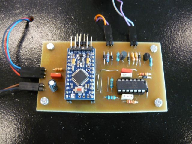
Mechanical constructionOverview of the work in progress versus the final result.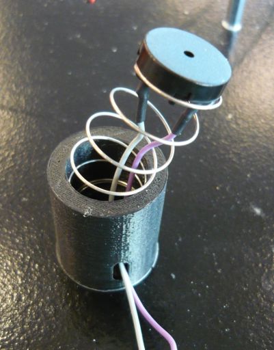
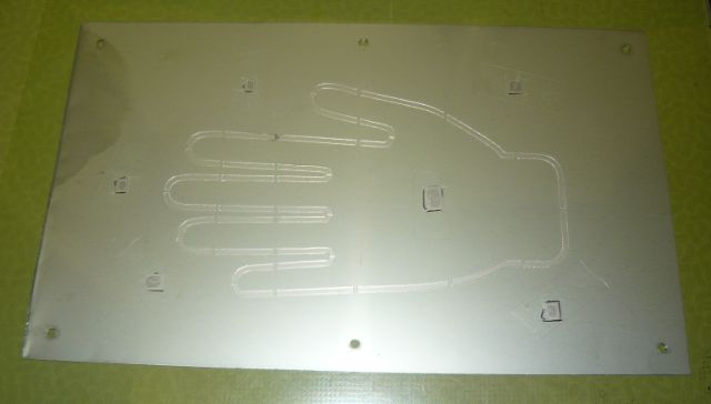
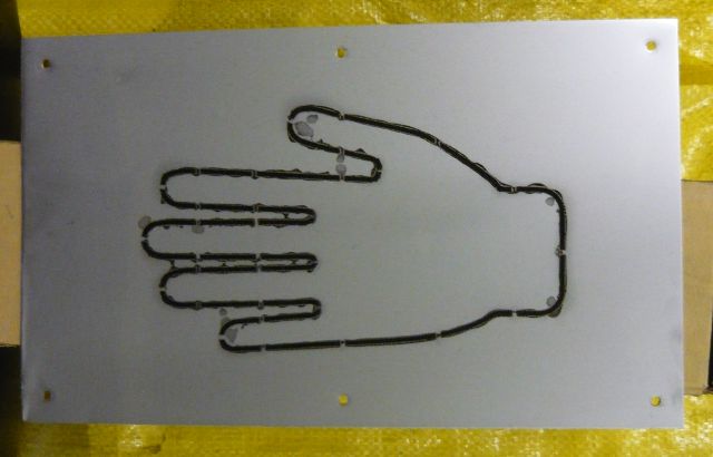

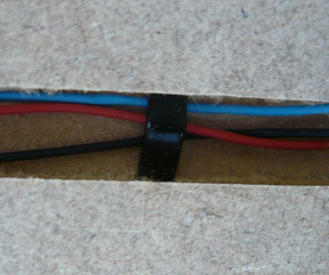
SoftwareThe software is built around a state-machine as shown below in simplified form. The major movement in the state-machine is the measurement sequencer. The peak detectors must be enabled and the analog hardware must settle before a measurement can be taken. This is especially important because the piezo-buzzer is used both as detector and speaker. Almost any state will go to idle directly if the hands leave the plates. The game only operates when you keep your hands on.
The code uses the Arduino framework, but many features program the ATmega328P chip directly. For example, tones are generated using hardware timer 1 and outputs on OC1B. This prevents software timing from interfering with the tone consistency. The analog to digital conversion is coded directly to the hardware ADC. The timing requirements and sequencing make it more appropriate to bypass the Arduino libraries. Care has been taken to reduce input leakage currents on the analog pins by disabling the digital input buffers on these pins explicitly. The WS2812B strip is controlled by Adafruit's NeopPixel library, with an addition to control the pixels in the HSV color space. The acrylic disc LEDs do use the Arduino infrastructure for PWM (analogWrite). Design documents and code
Posted: 2016-11-28 |
| Overengineering @ request | Prutsen & Pielen since 1982 |