

 |
 |
|
|
NoLoop - Serial and SPI isolator
Breaking ground-loops with galvanic isolation
Electronics work by interconnections. Normally, you'd think that a potential at
one point on a wire is the same everywhere. However, that is (mostly) not the
case and all kinds of aspects can pop up that make the potentials differ at
different locations.Old-timers may remember connecting a printer to a computer and getting zapped by the connector when touching both computer and printer at the same time. You'd expect both ground-levels of the computer and the printer to be at the same level, but they are not (due to capacitive/inductive coupling). The problem is much wider than the printer on a computer. Any connection you make may give rise to:
It is easy to imaging that, if your computer is part of such a ground-loop, then it may take permanent damage. Also other electronics take damage because signal levels are not there where they are supposed to be. You have to break the ground-loop to solve the problem. 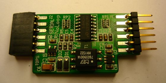 NoLoop Serial galvanic isolator (click to enlarge) 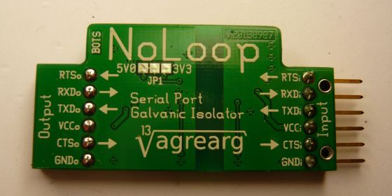 (click to enlarge) 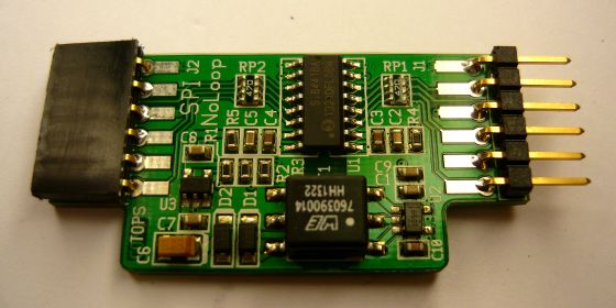 NoLoop SPI galvanic isolator (click to enlarge) 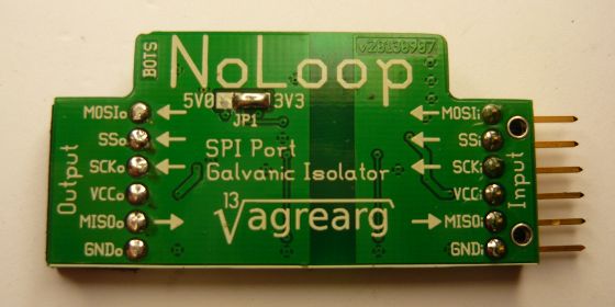 (click to enlarge) NoLoop is a galvanic isolator for both signal and power connections. NoLoop separates the in- and out-put breaking any existing of a ground-loop in that connection path. You can get your NoLoop at my Tindie store. NoLoop Serial's specs include:
note 1: use 5V version USB powered for loads ≥10mA. NoLoop
can level-shift for you if necessary.
note 2: a 10..22µF low ESR capacitor on the output is
required for reduced ripple at high(er) loads.
note 3: Using FTDI converters on USB and drawing more than 60mA at the
output requires adapting the USB descriptor (see FTDI documentation) to
indicate higher power consumption.
The schematics are available under CC-BY-SA-3.0 (mail me if you want the gerbers or sources): The signals are transfered with an RF transfer method (si844x datasheet or newer version si864x datasheet) and have only very little delay. Below images show the serial and SPI versions input/output signals. The propagation delay is less than 10ns, with some measurement correction due to probe differences. Power is transfered with a small 1:1 switching power supply and regulated with an LDO at the secondary side. The switching frequency is about 350kHz. The LDO can be set at 5V or 3V3 with a solder-jumper (default at 5V). 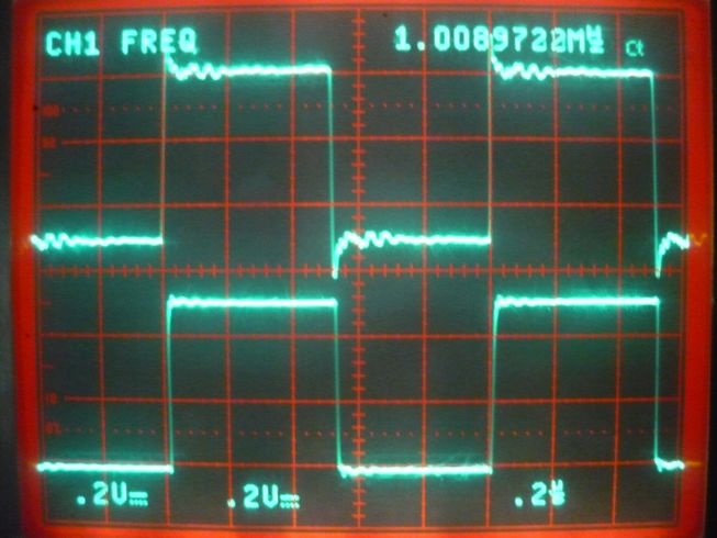 1MHz signal on NoLoop Serial; top: input, bottom: output (click to enlarge)
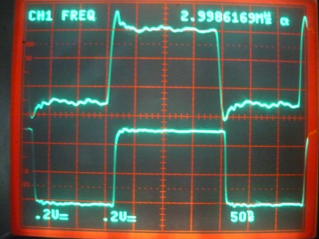 3MHz signal on NoLoop SPI; top: input, bottom: output (click to enlarge)
Posted: 2013-10-04 |
| Overengineering @ request | Prutsen & Pielen since 1982 |