
 |
 |
|
|
Lights Out, Turing Style
Circuit design
The design is based on the previous analysis of
calculating the game in a circular shift register. While designing, it occurred
to me that small extensions to the design would enable additional game play
features, such as replay and manual input. The final design has the following
features:
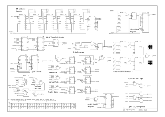
Schematic diagram of game play
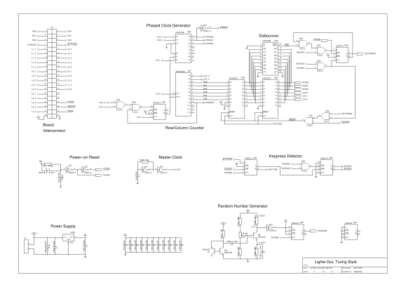
 Schematic diagram of debounced keyboard and support circuit
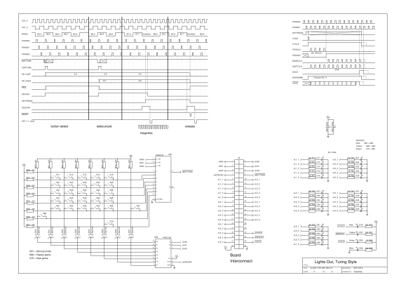
 Schematic diagram of keyboard and LEDs incl. timing
 Complete schematic as PDF. Gschem source of pages 1..3. Circuit description index
Clock GenerationThe system clock is a low frequency relaxation oscillator with a '14 Schmitt trigger, running at about 13kHz. The frequency has been chosen to give a scan-cycle time of ~20ms for the keyboard scanner. The clock is combined with the first two stages of a '4040 and a '238 de-multiplexer into a phased clock signal (PHASE0, PHASE1 and PHASE2), which are guaranteed sequential, separated and non-overlapping. A phased clock assures that events can be timed precisely in sequence and prevents glitches from propagating (CPUs use a similar method internally too). The clock phase generation is coupled with the keyboard scanner (see below).Power-on ResetThe system is initialized by a common reset circuit setup using a RC charge time coupled to a '14 Schmitt trigger. When the power is turned on, the RC delay holds all important pins at the reset level (CLEAR signal) and thereby initializes the logic to start in a known situation. The reverse diode (D71) is connected to prevent any latch-up when power is 'wonky' (input pins should never be allowed to be at a higher level than the power-supply).Random Number GeneratorThe board initialization for each new game is taken from an adjustable random generator. The source of random is a PN-junction in reverse (Q1 base-to-emitter). A high voltage applied at the PN-junction forces it into avalanche breakdown, but when this happens, the applied voltage is reduced through Q2 becoming active (the BE junction of a BC547B starts to break down between 7 and 8 Volts). The output of Q2 is amplified by Q3 in such way that the Q3 output bias is set at the middle of the '14 Schmitt trigger hysteresis, thereby allowing the Schmitt trigger to alternate at defined levels, but in a random fashion.The bias output of Q3 is adjustable with R105, which alters the position in the hysteresis curve of the '14 Schmitt trigger. This effectively biases the random towards '0' or '1', depending the position of R105. A '74 D-flip-flop latches a random value at each PHASE0 so that any reader on the other side will see consistent values. The random data is high frequency and inputs have setup- and hold-times, but the times may vary from chip to chip. The random data, as input to the game register and the replay register, may not be the same without the synchronization. Keyboard Scanner & DebouncerThe keyboard consists of a 8-by-8 matrix of switches (not all are used). The idea is to scan through each row/column combination and see if a key has been pressed.A '4040 counter is used to count from (row,column)=(0,0) to (7,7) and each key is sequentially selected using a de-multiplexer + multiplexer combination ('138 and '151 chips). Whenever a key is pressed, the output BUTTONX will be low for the appropriate coordinate. This is latched in a '74 D-flip-flop to generate a clock-pulse to capture the button press. A pressed button results in the recording of the coordinates in a '273 latch, but no key-press will be asserted if this is the first time detection. When the scanner returns to the same coordinate, some 20ms later, it will then cause the re-recording of the coordinates and push the previous coordinate to a second '273 (an 7-bit wide, 2-bit deep shift-register, as you will). If the first and second detection of a key-press are at the same coordinates, then the '688 comparator will be active and a key-press will be activated at KEYPRESS. This procedure effectively debounces the key. The de-activation of the KEYPRESS signal is dependent on the detection of "no-button-at-all". For each scan-cycle, it is recorded if any button is pressed (ANYKEY). Only when all buttons are released will the KEYPRESS be released at the end of a scan-cycle and the recorded coordinates cleared. This prevents key-rollover from being a problem A debouncing problem exists for coordinate (0,0), where a reset of the '273 latches would be the same as the detection of button (0,0). However, by using a static '1' at the input (bit 6), it can be determined whether the latch recorded a button press or the value was the result of a latch reset. It should be noted that the '4040 counter counts one position more than there are buttons. This extra value (EOSCAN active) is used to perform all necessary sequencing for (de-)activation of KEYPRESS, clearing of ANYKEY and (synchronous) reset of the '4040 counter. Debouncing any button-press is performed by the above described '273 latches with the comparator. However, the button-release debounce is not explicitly designed, but is implied by the setup. When a button is released and a complete scan-cycle causes the KEYPRESS to be deactivated, then the next scan-cycle may still detect the released button due to release bouncing. But, because it is required to detect pressed buttons for two scan-cycles, it will be improbable that the button is reasserted. With the speed of the scan-cycle, it can be virtually guaranteed that there will be no false detection (bounce-times are generally <5ms and humans pressing buttons will take >100ms to press twice for the very fast; mostly well over 250ms). For the observant; debouncing the key press is strictly seen not required (if random glitches can be guaranteed to be non-existent). The calculation cycle is 128 clocks, and that would prevent re-assertion of the key press. However, key release must be debounced. When a button is released, then the calculation cycle is most likely over (takes ~40ms). Bounces on the release would re-initiate the calculation cycle on (probably) the same button, which effectively results in two key presses and that means the same game-change twice; i.e. no change at all. Therefore, some form of deboucing is required (and the presented design is just nice). Game and Mask RegistersThe game's state is recorded in a 64-bit shift register, as previously described, using five '164 serial-in-parallel-out registers (40 bits) and a 4557 programmable shift register set at 24 bits. The output Q7_7 is fed back into the input D0_0 using a feedback calculator, which selects the appropriate calculation.The mask register consists of two '165 parallel-in-serial-out shift registers and a '74 D-flip-flop to create a 17-bit long register. The parallel load function initializes the register with the required pattern at each calculation cycle. The mask register is stuffed with zeros when it is shifted. Cycle CountersThere are two distinct cycle counters. The first is built around two '163 binary counters with synchronous reset. It counts 128 clocks to set the modulo 64 cycles required for pattern reemergence asserting XCYCLE when reaching 128 counts.The second counter counts 64-(row*8+col) counts and is built with two '193 binary counters with asynchronous parallel load functionality. At the start of each cycle, the row/column value of the pressed key is loaded and the counter advances up to overflow (POSCNT), which signals the correct amount of counts. Please note that "64-(row*8+col)", in counting terms, is the same as: "start at row*8+col and count until 64 is reached". Cycle GeneratorEach calculation-cycle is timed from a KEYPRESS event and locked into a '74 D-flip-flop. The LOAD signal is activated for one PHASE0 active time to load the mask register and sets the counters to their start position. During the 128 count long cycle, the first part is used to advance to the 64-(row*8+col) position until POSCNT. Then, for the remainder of the 128 count cycle, the mask register is advanced and stuffed with zeros.The end of the cycle is indicated by XCYCLE and combined with pattern validity checks to form EOCYCLE. EOCYCLE then terminates the cycle at the next PHASE0 clock. It is assured that no new cycle can start before the previous cycle is terminated. The prevention is done by a feedback of the CYCLE signal at the KEYPRESS input D-flip-flip (U19), which normally starts the cycle. It should be noted that prevention of restarting a cycle is more of theoretical than practical importance. The chance of a cycle to last much longer than 128 clocks is small because it can be expected that the random generator will generate a valid pattern quite effectively. Even a full 64-count extension of the cycle would only last ~20ms, which is not enough for a secondary key press. Game Initialization and Valid PatternsThe board is initialized when the "New Game" button is pressed (location (7,5)). The detection of this button is limited to the determination that a button in row 7 was pressed, which is sufficient for the intent and saves gates. The NEWGAME signal is generated from KEYPRESS for this specific button.The NEWGAME signal is used as a selector in the feedback generator, enabling the D0_0 signal to carry random data, which is shifted into the game resister. This is all performed as if it were a "normal" calculation cycle with the exception that the NEWGAME signal dictates the changed feedback behaviour. The NEWGAME signal forces the CYCLE to remain active for as long as it takes, beyond 128 clocks, for a valid pattern to emerge. The valid pattern calculator uses the two "quiet" patterns to generate the VALID signal, which becomes active if, and only if both quiet patterns return true. Each quiet pattern must have an even number of active inputs for a valid board. The validity is checked with two pairs of cascaded '280 parity generators, which return even/odd parity for each of the quiet patterns and combined to form the VALID signal. If the random generator is set to generate (too) many '0' bits, then it is possible for empty patterns to be the initialization's halting point. If, for example, 'on' lights only are visible at the column 5 position after the initialization cycle, then a single shift adding an additional 'off' light shifts the turned-on lights beyond the border of the visible board. This will stop the initialization cycle because "all-lights-off" is a valid pattern; be it the final solution. Preventing this from happening is actually a difficult task and would require the accounting of all 25 lights at initialization. At the risk of being called lazy, it is suggested that this task is left to the reader or anyone who wants to make a replica. Manual ModeAn additional game-play is added by changing the mask in such way that it only carries a single '1' bit located at the position of a button-press on the game board. This makes it possible to change all 25 lights on the board individually and may be used to enter patterns manually.The manual mode is enabled/disabled in the same way as in which the "New Game" button functions. However, in this case it is activated on button position (5,7) and only the column address is tested (any button in column 7). The second difference is that the button press toggles the manual mode on/off with a '74 D-flip-flop setup in divide-by-two (or toggle) mode. The valid pattern indication is available when individual lights are toggled. The VALID signal is always indicative of the pattern's solvability. Replay GameA second 64-bit register (a 4557 set at 64), the replay register, is loaded on every board initialization, which remains intact until it is overwritten with new initialization data. Manual mode also loads the replay register on every cycle with the current game register. The data in the replay register is rotated modulo 64 on every cycle except for the new game and manual cycle.When the Replay-button is pressed, the replay register is passed through the feedback generator and loaded into the game register, which restores the stored pattern from last game initialization or manual change. Button (6,0) is used for this purpose, but the only test is for column 0. The activation is similar to the new game button (except for the propagated polarity of the signal). Feedback CalculatorThe central calculation point is the feedback calculator. Its primary function is to make the game register a circular shift register and to apply the mask calculation. The D0_0 signal becomes the output on coordinate (0,0) after the next shift clock pulse SHIFTCLK, i.e. and . The pure logic feedback function can be illustrated with a Karnaugh diagram* for D0_0. Please note that REPLAY and NEWGAME cannot be active at the same time because the button setup will not allow it. This specific condition is marked don't care with '-' and is used to reduce the equation.
D0_0 = NEWGAME•RANDOM + REPLAY•DX + NEWGAME•REPLAY•(POSCNT•MASK•Q7_7 + POSCNT•MASK•Q7_7) The equation is implemented with a '51 combi-gate chip and left-overs from '00, '10 and '27 gates. LEDs, logic and powerThe LEDs for the game board are placed in a 5-by-5 matrix on top of the buttons. The LEDs are a "super-bright"-type to reduce the current draw from the logic chips. The used HC-logic is poor at sourcing current (needed for the positive logic in the game register). Therefore, the current is limited to about 2.5mA per LED, which guarantees that the outputs are not suffering overload and would fall under safe logic levels for the valid pattern calculator. Surely, the outputs could be buffered, but that would cost four more chips and a lot of extra work.The other LEDs on CYCLE, VALID and MANUAL signals use negative logic and the HC chips sink the current. All 74-families sink current better than sourcing it, but HC(T) is still poor at it and 20mA is just too much. Besides of being good for the HC-chips, the reduced current draw also makes total power consumption lower and reduces the strain on the 7805 regulator to below 1W worst case (the 15V input level is needed for the random generator). For the observant, no pull-up resistors are used in the design, they are mostly an old habbit having worked with too many logic families with different requirements. Then, while working on the diagram, and having over forty pull-up points and still expanding, it was needed to go reading a bit to refresh the memory cells. The 74-HC(T) family has CMOS inputs and the family datasheet explicitly allows for tying both to GND and Vcc. Section 7.4 of Philips' (now NXP) HC/HCT User Guide; the datasheet writes: "Unused 74HC and 74HCT inputs should be connected to VCC or GND, either directly (a distinct advantage over LSTTL), or via resistors of between 1 kΩ and 1 MΩ.". So, gone are the pull-ups and everything becomes easier. Other design pointsThe button coordinates used for "New Game", "Replay" and "Manual Mode" are not chosen randomly, but 1) because of the row/column position for easy detection (i.e. row 7, col 7 and col 0) and 2) because the positions will not affect the game board. The second premise is only really required for manual mode. Each button press will result in a full calculation cycle. Manual mode will change the underlying game register at coordinate (5,7). However, this will not matter because there are no visible lights in that area, seen with +/-1 in x and y.Next part: Building the game Note:
* Never expected to use a Karnaugh diagram anymore after learning about them many, many years ago...
Posted: 2011-09-25 |
|||||||||||||||||||||||||||||||||||
| Overengineering @ request | Prutsen & Pielen since 1982 |