
 |
 |
|
|
Active Flipper
7x7 Flipdot module, large and small
Ever since our local hackerspace got a hand on a
couple of those large flipdot signs, I've had that itch to do something special
with those flipdots. Hacking the signs and
experimentation with new flipdots was not
enough. What about an inexpensive module for general use? There must be others
interested in using flipdots, that was my thought.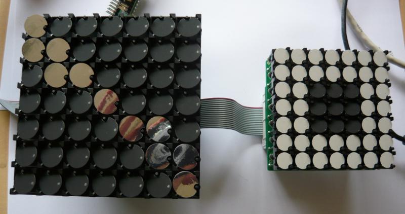 The basic idea was to make 7x7 modules, consisting of seven 1x7 flipdot strips, and place then in a matrix. The greatest challenge of the flipdots is the requirement of AC currents flowing through the coil(s) to flip. A single strip can be run with H-bridges, as demonstrated in the fliptest experiments. However, doing so in a matrix results in quite a different component setup. The standard way of matrix control is to ensure that each and every cross-point in the matrix is isolated with a diode to ensure that only one point in the matrix can be activated at the same time. This works very well for DC, but is insufficient when the current needs to be able to flow in both directions. The solution is adding more diodes and separating row-drivers in high- and low-side switches that connect to the diodes. The column drivers can then be simple totem-poles to provide high- and low-side for the second connection. This setup effectively creates a double or "bipolar" matrix, where you can drive each matrix intersection in either direction. There are two disadvantages with a bipolar matrix setup with respect to H-bridges. Firstly, there are extra diodes involved, which have to hold to the pulsed currents and they dissipate heat due to the added voltage drop. Secondly, a MOSFET H-bridge uses the internal body-diode as fly-back diode. This does no longer function on the row-drivers because the added diodes block the body-diode. Two extra diodes have to be added for each row for fly-back to power-rails and ground. 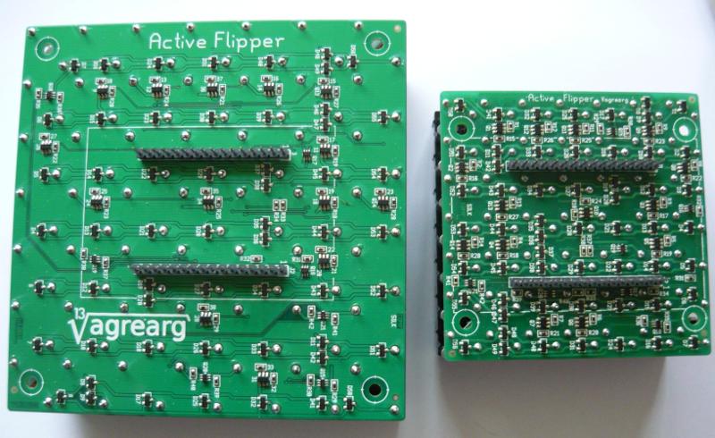 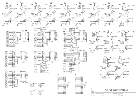 Active Flipper Small diagram as PDF. The large module is the same as the small module. The only difference is that the physical pixel layout is X/Y-mirrored (can be compensated in controller configuration). The number of control signals needed to drive a bipolar matrix is twice that of a normal matrix. This calculates to 28 controls (2 times 2x7) for a 7x7 module. A solution with eight H-bridges would result in 112 (7 times 2x8) controls. The factor 4 reduction in control signals is well worth the effort. The number of components is another point (not accounting passives). An H-bridge solution would require 8 high- and 8 low-side MOSFETS. With the low-side in 2-in-1-house would result in 96 (8x12) components. The bipolar matrix uses 14 high- and 14 low-side drivers plus 2x49 isolation diodes and 2x7 fly-back diodes. That gives us a component count of 14+7+49+7=77 (with 2-in-1-house diodes). So, either way, a bipolar matrix is cheaper to make. The compromise is that only one flipdot can flip at a time. The backside of the modules has two 16-pin single-row pin-headers (100mil) which carry the 28 control signals and the power supply. You can use your own interfacing directly at the module's connections, or you can use a specially made Active Flipper Control for high-speed control and high-level commands with multiple protocols.
The Active Flipper Control board was designed to flip the dots at very high speeds in mind and with interfaces for SPI, I2C and Serial (default 115k2 8n1). The controller also monitors the power supply and actively controls pulse-shaping for optimal performance. The control board is designed in such way that the modules are cascade-able through a 16-wire IDC connection. Up to 16 modules can be cascaded when using SPI or Serial communication and up to 112 using I2C. However, practicalities like bus-load and power supply currents need to be taken into account when linking more than 16 modules in I2C mode. Note: all signalling on the 16p IDC connector is at 3.3V. The I2C connection is 5V tolerant, but SPI and serial are 3.3V only. The Active Flipper Control has a command-set that allows for high level commands to be sent. The commands can be sent simultaneously via all three protocols. The commands include:
A console interface is provided on the controller (running at 115k2 8n1), which can be used to configure and debug the controller. Signalling on the console is at 3.3V only. 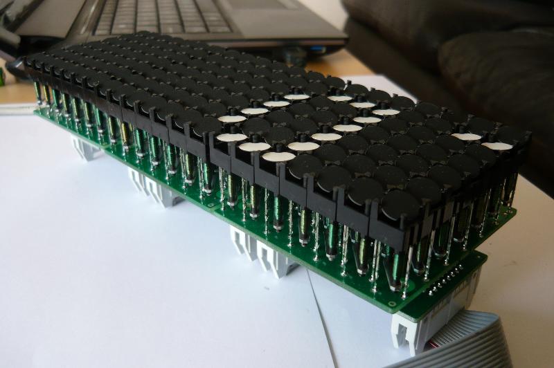 The controller is able to flip the entire module in about 30 milliseconds and is capable of 30 frames per second at maximum input voltage. It should be noted that the inertia of the flipdots is rather high and they are not capable of flipping this fast. The small (10mm) dots take 30..40ms and the large (15mm) dots take 40..60ms to flip (approximately). The controller also includes intelligence on the current state of the flipdots. If a new command does not change the state of a flipdot, then it will simply skip that dot. It should also be noted that the controller's communication input runs asynchronously from the actual flipping of the dots. This means that you can send commands to a cascaded set of modules and they all flip at 30 frames per second. The highest communication load happens when 16 modules are updated with a "draw all pixels" command, which requires 8 bytes per module. The slowest communication speed (assuming serial) for updating all modules is 16 modules * 8 bytes * 10 bits * 30 fps = 38400 baud. The default is set at 115k2 8n1, which is three times faster and helps to mitigate inter-module communication latency. The controller can be fed with a power supply ranging from 10.7V to 18.0V and automatically regulates the timing based on the available input voltage for proper current-pulse shaping. The controller will enter Undervoltage Lockout if the input voltage drops below ~10.65V and a red LED will light up. The module will flip all dots in under 40ms when the input voltage is at minimum level (or just over 25 frames per second). The power supply should be capable of >800mA surge currents per module at maximum voltage (i.e. three cascaded modules require a PSU capable of 2.4A surge currents). Alternatively, you need to have a large (220..330µF times the number of cascaded modules) low-ESR capacitor at the PSU. Lower input voltage reduces the surge currents proportionally, but also slows down flipping. The exact shape and level of the surge currents depends highly on the commands sent and the induced flips. A problem with the current design is the possibility of pulse-capacitor burn-out. Every flip involves a transient current from the pulse-capacitor to the flipdot-coil and a much higher (surge) current from the power supply to reload. The ESR, and therefore dissipation, becomes a problem at high voltages and very fast flipping. The pulse-capacitor (33µF) at 18V with 1500 flips per second reaches temperatures that are well above 85°C, and probably burns out when used at this level for prolonged periods. The controller needs to be redesigned (which was already planned) to correct this issue with lower ESR capacitor(s). 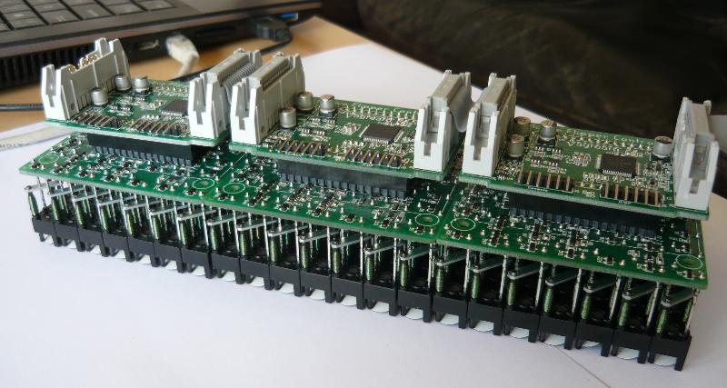 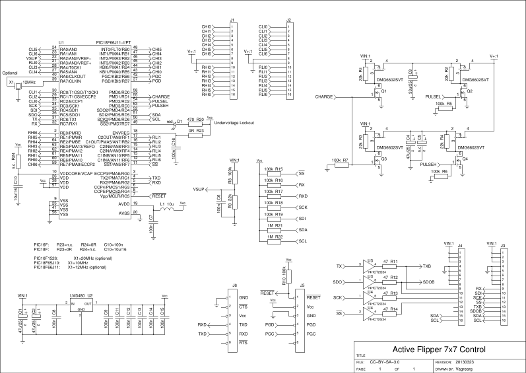 Active Flipper Control diagram as PDF. A quick demo...
Posted: 2013-04-18 |
| Overengineering @ request | Prutsen & Pielen since 1982 |