
 |
 |
|
|
504 Segment Clock
A 7-Segment Clock Done Differently
If you need a clock in your house, then you need to do so with style.Well, that is at least my conclusion when I make something. The last clock I had in my house was the clock on the old VCR. You know, that tape thingy, which got scrapped many years ago. And, no, that clock was not a 12-o'clock flasher. I do have a wristwatch, but you know lazy when you know it. Time to make a timepiece. It is apparently a human obsession to make clocks in all forms and measures. Therefore, time for me to join the club and make one too. And, with an over-engineering principle, a normal clock will not do. Hence, the 504 Segment Clock. 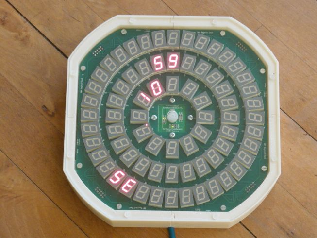 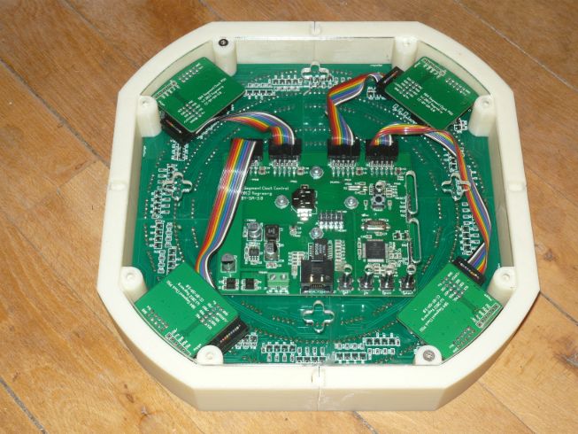 The ideaThe above images are iteration three of the design (iteration four will have white PCB silk). The original idea was created about two and a half years ago, when I decided that a clock in my house was appropriate and a spark of design-wit rang through my mind. What about creating a 7-segment clock, but orient the displays in a traditional circle... After an evening of experimentation it was clear that it would work out fine and a real design was started.Having many features in the 504 Segment Clock is a matter of honor. When you create something so outrageously strange and complicated, then it also must have lots and lots of (superfluous) features. They therefore include:
The designThe design for iteration three is shown below (click to enlarge):
The lot of the design-files, including the current firmware is available from Gitorious at https://gitorious.org/504segclock/504segclock. It should be noted that the holes for the buttons in the back cover Plexiglas plate are slightly off. I need to find out what went wrong and fix it. Also, I have to get new buttons with a longer stem to get them just right through the plate. The implementationThe practicalities of designing the 504 Segment Clock were a lot more challenging than at first anticipated. The PCB with the 7-segment displays would be large and therefore expensive. However, it turned out that it could be easily divided into four equal quadrants and then combined again with a sensor-board and a control-board at the back.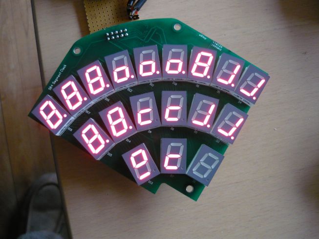 The first iteration of the control-board had all the sensors on-board. They were placed below the actual display-plane at 2.5cm depth. It turned out to be a bad idea as the light sensor would have too much shadow and the movement sensor would be restricted too much too. 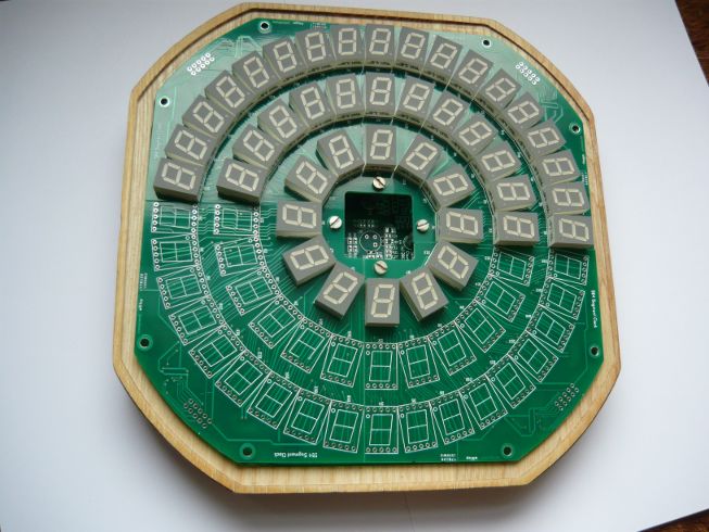 Above image also shows the first iteration of the case. It was thought that the hackerspace's CNC mill could be used to mill out a wooden case. It would have been nice, but the CNC mill was so bad at keeping measure that the case was off by over 2mm (and 1mm in the other direction...). An unusable proposition and an alternative was deviced to use 3D printing. 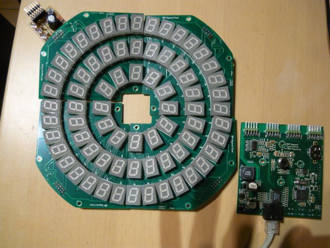 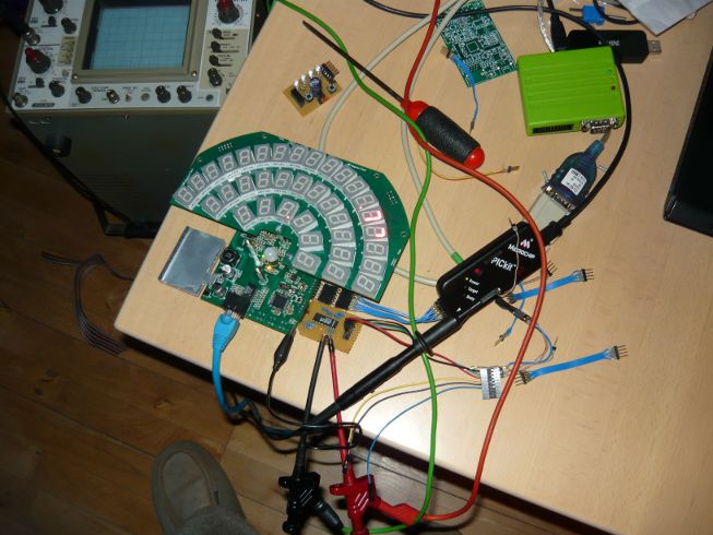 During testing, it was also noted that the power-supply was under-dimensioned. Although the switcher could supply the board(s), it got quite hot and the hammering PWM of the display quadrants meant that it was not possible to have a very nice 3.3V supply (had ~250mV ripple). Above image shows an aluminium cooling fin attached to keep it all in reasonable bounds. A second iteration of the control-board had a larger (6A) PSU designed on it, but that turned out to be tricky too. Finally, the control-board was redesigned only to supply the control-board and sensors. Each display quadrant was to have its own PSU. 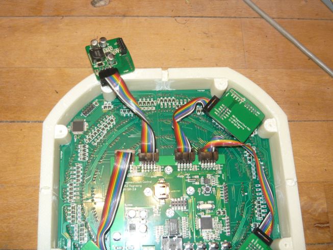 NTP synchronizationThe NTP synchronization works quite well. It was a lot of experimentation to get an 8-bit processor to behave properly with a complex protocol like NTP. The first thing that needed to be done was to eliminate all complex algorithms and settle for a simple solution to get quick and stable time convergence. The implementation adjusts 1/4 of the difference at each NTP round-trip and keeps track of a local drift variable (1/256 millisecond) to sync the local crystal. After a while, you get at most a ±1 millisecond adjust and a nice graph to show stability.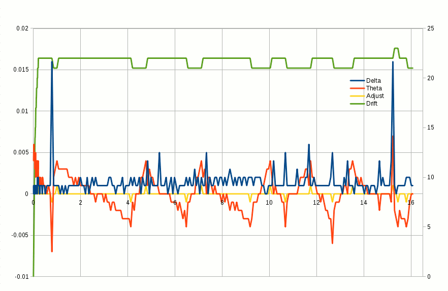 The horizontal axis is in hours. There are 290 samples and about 16 hours of measurements. The green line is the drift variable (axis on the right). The delta (round-trip to server) and theta (difference from server) variables are blue and red resp. (see the appropriate RFC for details). The yellow line indicates each instance where a millisecond is added/subtracted from the local clock. The above samples were taken with variable intervals. The actual interval will adaptively increase/decrease exponentially (between 16 and up to 256 seconds) when synchronization is detected. The control-board has a static deviation of 72µs per second (or 72ppm), which indicates that the crystal is not running at exactly 25MHz. The average round-trip (delta) is 1.3ms ±1.5ms and the deviation (theta) 0.72ms ±2.25ms. The 504 Segment Clock shows time within few milliseconds of the time-server. I'd say: mission accomplished. Remote controlThe 504 Segment Clock can be controlled through the Ethernet connection. A simple netctl application is included in the git sources. Sending specially formed UDP packets on port 0xc10c (49420) to the clock will control what is shown. The sample application sends 10 updates every second (about 12kByte/s traffic) which update each and every segment on the displays. The video below shows the remote control in action and also showing an alternative clock display emulating the handles of an old-fashioned clock.A QT application is planned to make a more visual impression on the remote control and such app may be relatively easily ported to a droid phone (if I ever get a "smart" phone). Next workNext will be to work on iteration four, which should be the final version. Large PCBs have become cheaper, so it is more appropriate and easier to use them. It combines all major components on one board and has SMD headers to prevent the pins protruding on the top. It is not yet clear if a single PCB on the back, with control and PSUs, will be done. But that is yet an option if I get it to fit.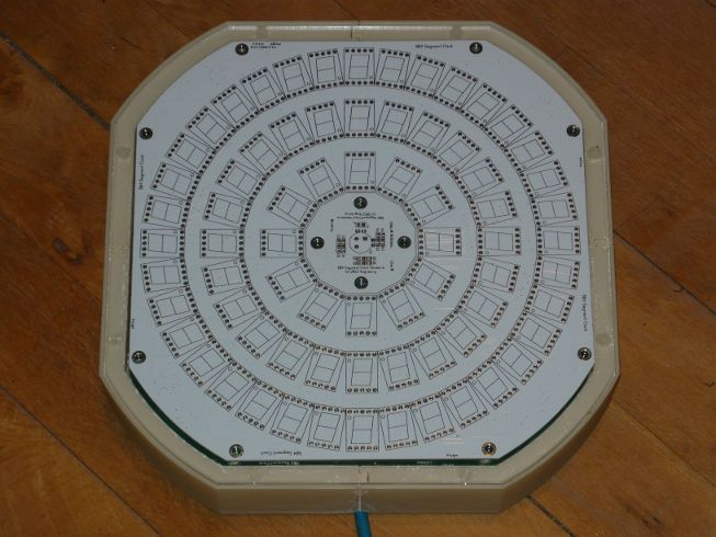 And then, the firmware needs a lot of work too. Most things are implemented, but the RTC needs to sync the running clock correctly when not running with NTP sync. Configuration through the buttons needs a cleanup and some eastereggs must be rethought. If there remains space in the flash, IPv6 should be an option too. Finally, I need to have some thoughts on selling this clock. It is not going to be a cheap one to buy, but it surely should be a nice one to have :-) The estimated sales price is €459,- or $625,- at low production volumes (≤10). Inquiries are welcome. Video
Posted: 2014-01-11 |
||||||||||||||||
| Overengineering @ request | Prutsen & Pielen since 1982 |