

 |
 |
|
|
{Avr|Pic}Stamp
Simple, fast, lots of I/O and serial
You often look for a quick-and-dirty way to hack something together when
prototyping. So do I and usually require a simple set of features like:
After calculating a bit, it was determined that the price-target only would hold at sufficient quantities (i.e. >100), but at production of 10 at a time it would be a target price of about DKK 125,- (~22USD; ~17€). Still a lot better than an Arduino and it matches nicely with other bare-boards I've seen so far. The price is still a very tight squeeze and volume is the only way to get any real money out of this. But why stop at AVR? There are people who like AVR and others who like PIC. So, make both... BTW, I got quite some comments on "why not buy a teensy" or other "board xyz"? Well, simply because the import duties are too high. The problem is that when you buy from outside the EU, as a private person, you are taxed with local VAT and, if unlucky, an import-handling-duty. That makes a 13USD teensy board into a 39USD import (and you need to add tranport costs as well). The {Avr|Pic}Stamp boards are designed to be cheap here in the EU. The transport cost is also low, as I can mail them as a letter (in the order 1..4€).
What does it look like: 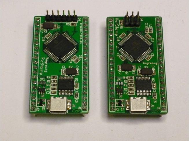 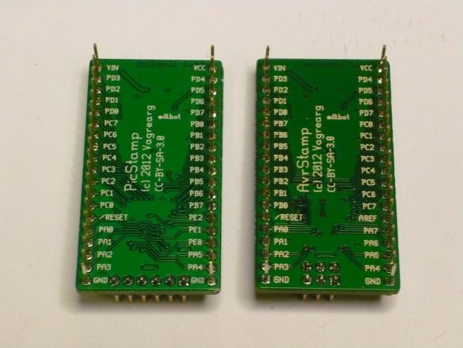 AvrStamp: 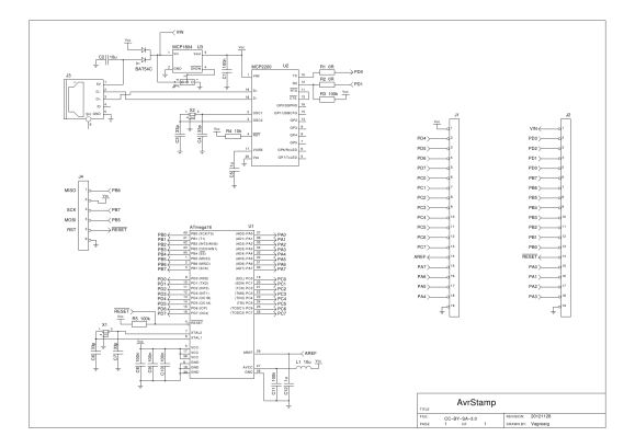 PicStamp: 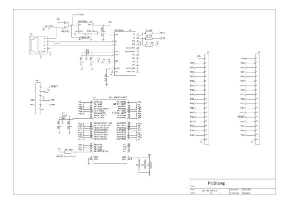 You can get the diagrams as PDF. The first version has only two real errors. The crystals are 5.0x3.2mm size, whereas the footprints were for the 3.2x2.5mm version. I do not remember when the change happened, but the larger ones fit when squeezed. The smaller crystals are more expensive and I need to check if I can get away with the larger one on the board, physically, when the footprint is changed. The second problem is that a trace is missing on the AvrStamp programming header, the reset line, and that means that it doesn't work. The signals are on the pinheaders, so that is a workaround for now. One option worth considering is the use of solder jumpers instead of 0Ω resistors to isolate the TX/RX pins. Also, the MCP2200 should have some solderable pins on the board when the 0Ω resistors are removed so you can get to the function separately. However, using more than 19 0.1" header pins would make the board longer than 50mm, which is not nice seen from a Seeed/ITead PCB sourcing perspective. Anyway, the boards do function as expected otherwise and I programmed a convoluted blinky with timers and serial I/O. Both boards on a breadboard: 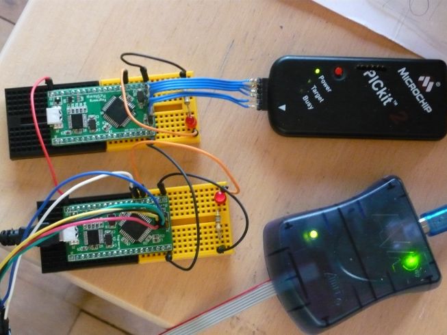 The blinky code is available as a tarball:
Posted: 2012-12-31 |
||||||||||||||||||||||||||||||||||||||
| Overengineering @ request | Prutsen & Pielen since 1982 |